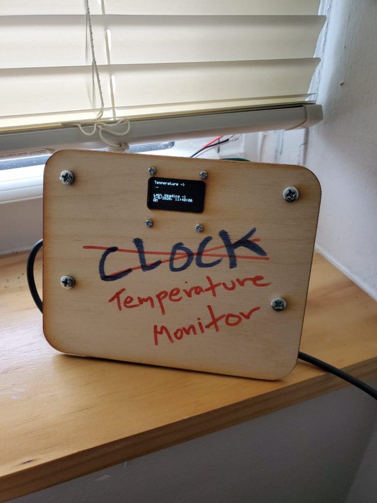
The Project
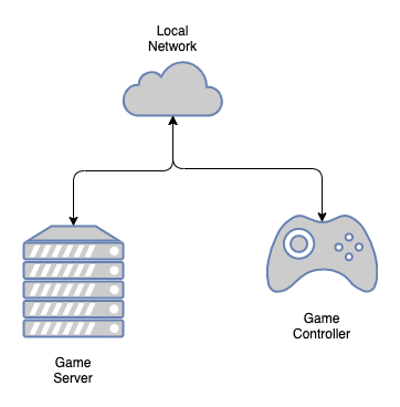
A device that records environmental data over time and send it to an online database.
Parts
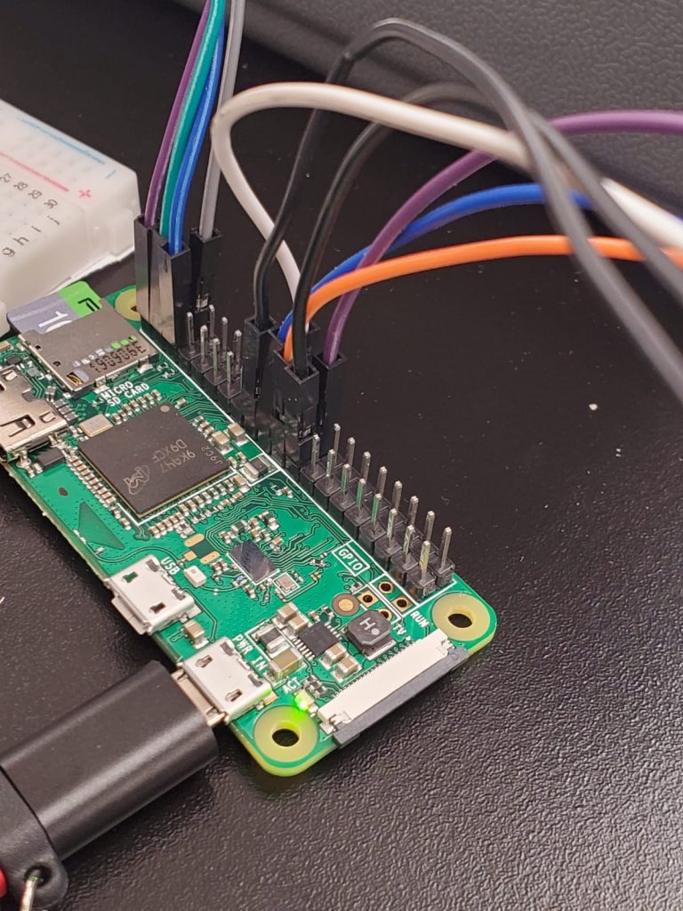
- Raspberry Pi Zero W
- SSD1306 Oled Display
- MCP3008 Analog to Digital Converter
- TMP36 Temperature Sensor
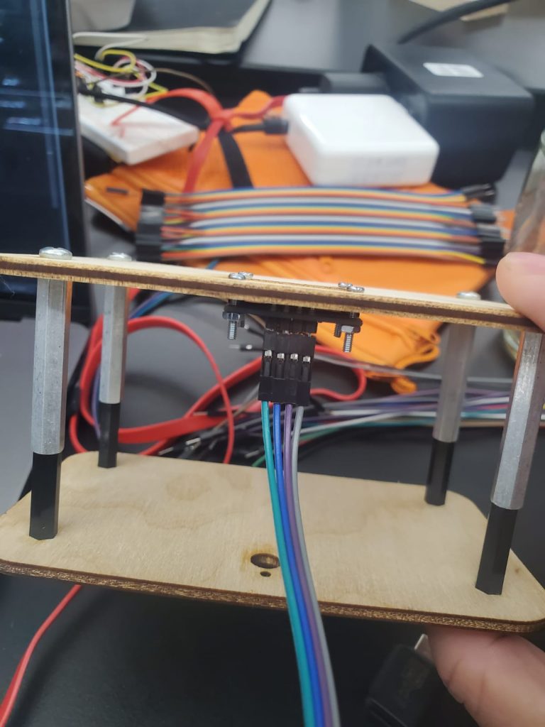
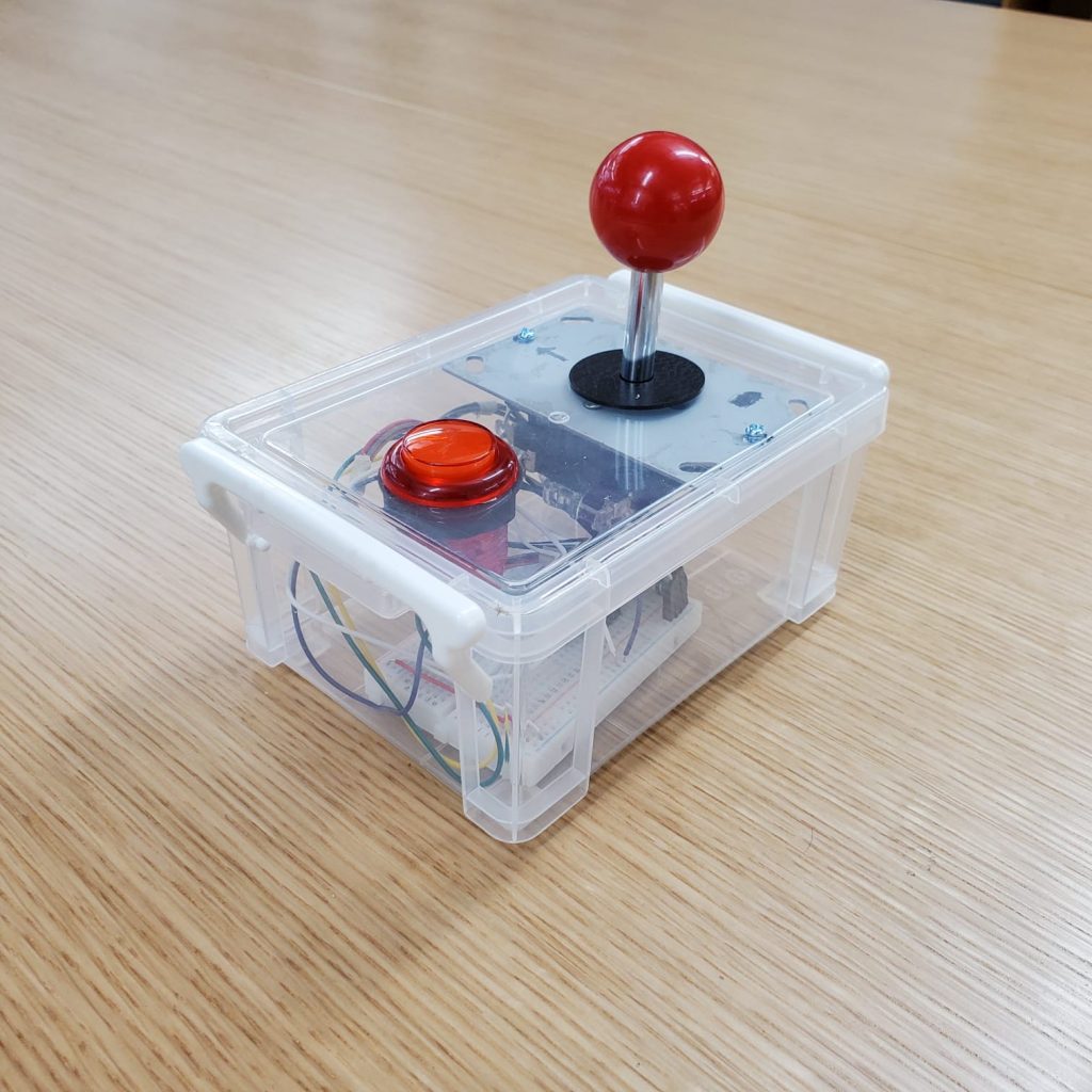
- Plywood and Standoffs (for the enclosure)
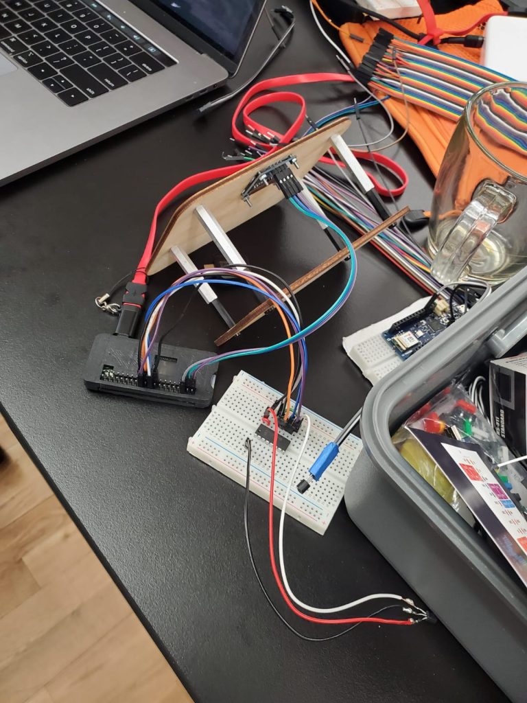
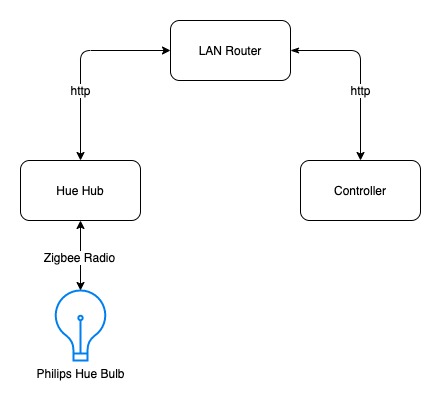
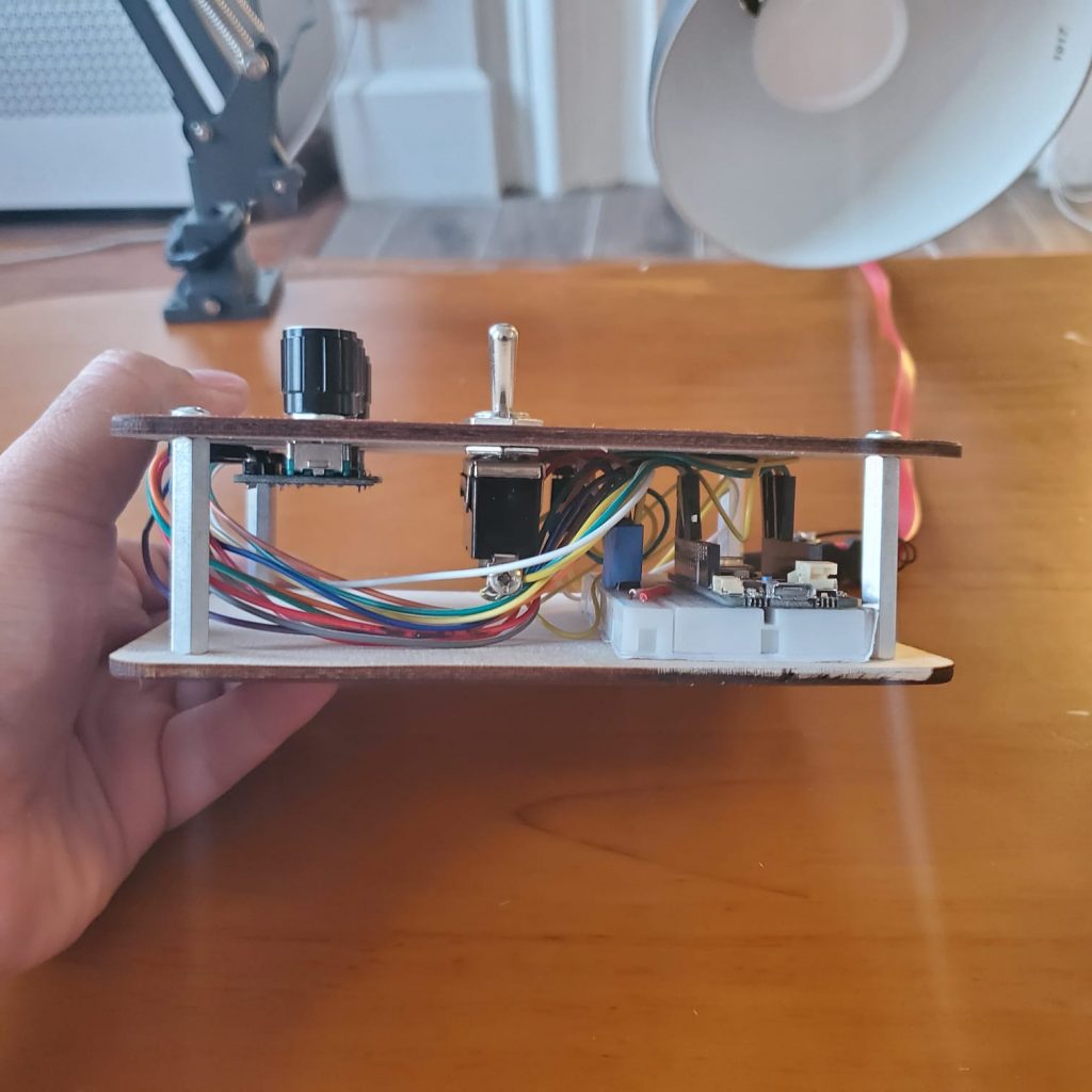
How it Works
The entire device runs on the Raspberry Pi Zero W. The display and sensor are passed through the GPIO pins of the Pi. I used cron job to run a node.js script that records the temperature every 5 minutes and sends it to the server.
Some Things that Didn’t Work
- I tried to use a MAX4466 Mic Amp to record noise pollution level. However,, it was not sensitive enough.
- I also tried to use a Yeti USB Mic to record noise pollution, but it also didn’t work out because the pi needed an external sound card.
- I wanted to do an aruino based device and a raspberry pi based device running side by side to compare the two, but unfortunately I ran out of time.
Links